What needed solving.
Multiple controllers need a stable, repeatable position but stock clamps compete for board edge space and swapping hardware is inconvenient. The mount transfers pulling loads into a fixed front jaw while a rear screw-driven jaw locks a dovetail sled into place.
- 01Controller + board dimensions
- 02Parametric base and sled
- 03Fit pieces + assembly renders
Simplified from the implementation and project notes.
How it fits together.
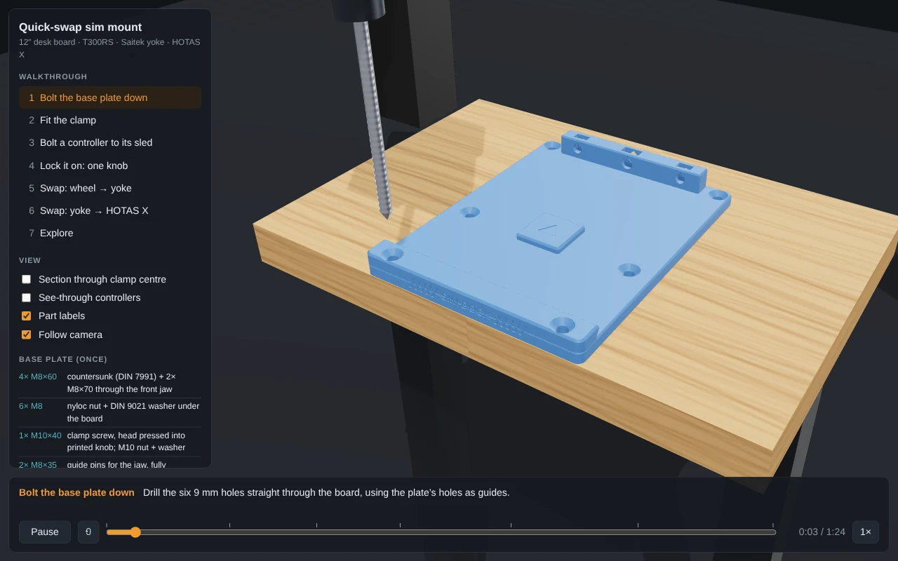
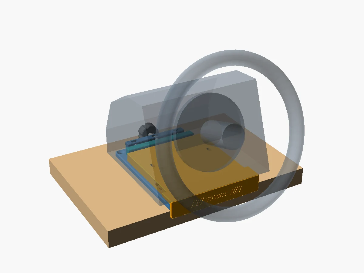
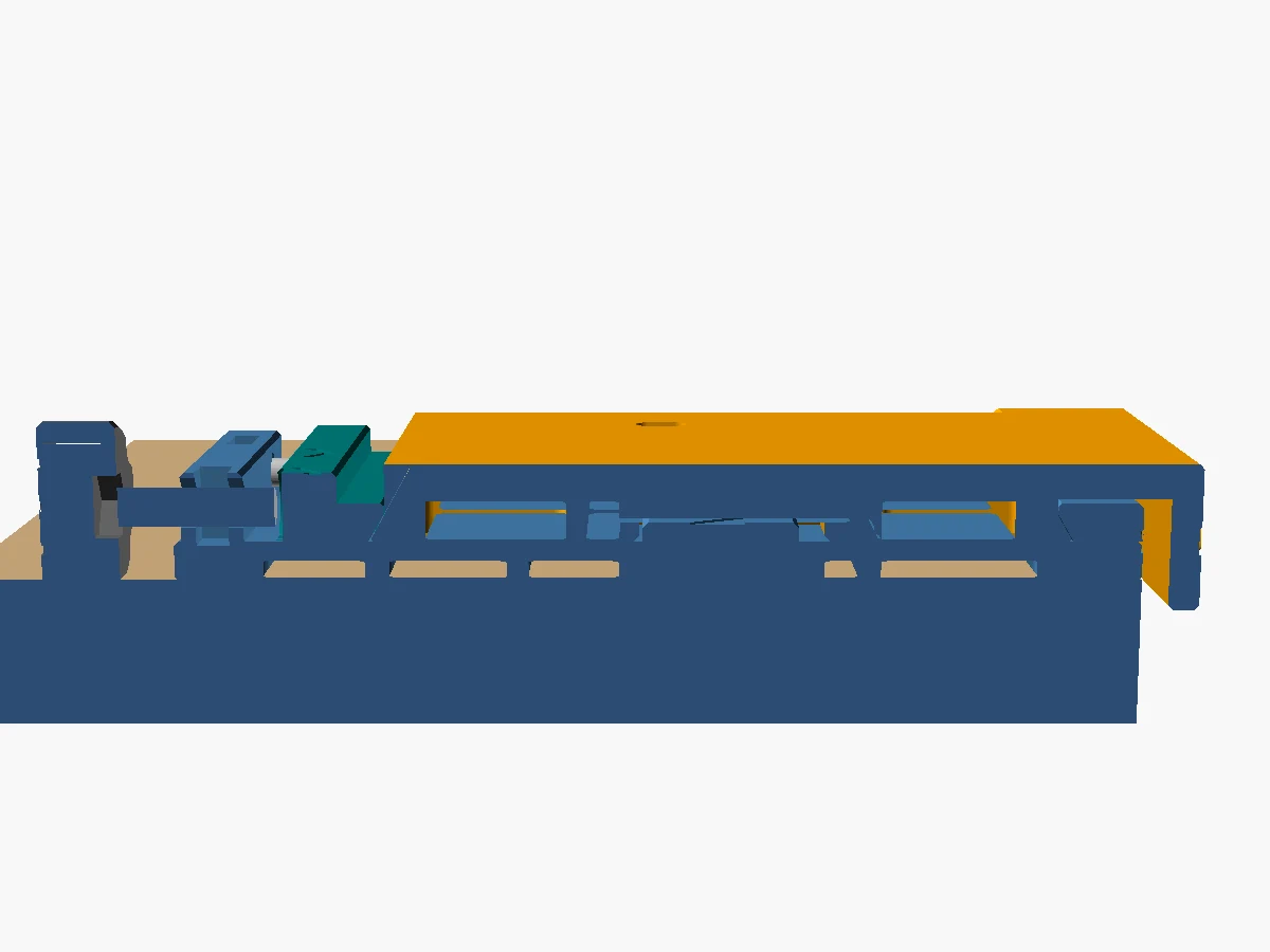
The model separates a bolted base plate from per-device sleds with matching 60-degree dovetails. A moving jaw slides on two M8 guide pins and an M10 screw pushes it forward; the fixed front lip takes pull loads. A keyed 40 mm interface locates sleds side to side. Controller-specific geometry handles a T300 wheel, yoke, and HOTAS X; where hole dimensions are not confirmed, the documentation labels placeholders and uses straps rather than invented fastener interfaces.
One OpenSCAD source generates printable parts, assembly-position STLs, and previews. Parameters cover board dimensions, front extensions, HOTAS spacing, and device fit. A browser walkthrough illustrates installation, swaps, section view, dimensions, and free orbit. Hardware fasteners and print orientations are documented alongside the model.
The design includes explicit fit-before-build steps: measure board dimensions, confirm yoke hole centers, print thin fit plates, and check controller envelope dimensions. This is a reproducible design workflow with physical fit gates rather than a claim that every device model has been verified.
Building and checking it.
Set the board parameters, render the base and chosen sled, print the parts in their stated orientation, bolt the base through the board, and swap sleds by loosening the rear knob, sliding back, lifting, and reseating. Before drilling/printing, verify board attachment and device-specific hole and envelope assumptions with fit pieces.
The explorer can be opened as a static page; it loads Three.js from a CDN. OpenSCAD is required only to regenerate geometry.
Yoke hole spacing is explicitly a placeholder and must be measured. HOTAS retention uses straps because threaded mounting points are unconfirmed. The mount's stiffness depends on board and rig attachment. No load, fatigue, or safety test is reported; the visual explorer demonstrates assembly sequence, not mechanical qualification.
Source notes
Based on repository code and project records reviewed on October 30, 2026. Historical checks are described as recorded, not rerun for this article. Screenshots, renders, and mockups are labeled individually.
sim-rig-mount/README.mdsim-rig-mount/sim_mount.scadsim-rig-mount/build.shsim-rig-mount/explorer/index.html