What needed solving.
Two round guides can overconstrain alignment when their spacing is imperfect. The proposed experiment asks whether a round primary guide plus a slotted secondary guide improves planar capture while retaining yaw control, compared with two round guides and a looser two-round alternative.
- 01Alignment hypothesis
- 02Parametric fixture + coupons
- 03Planned physical comparison
Simplified from the implementation and project notes.
How it fits together.
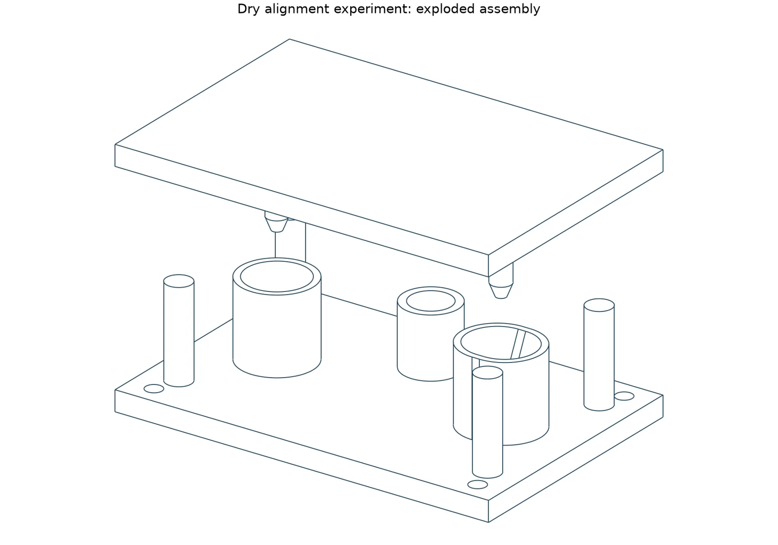
The parametric CAD defines receiver and moving plate, guide pins/bores, connector dummies, axial stops, fit coupons, and biased parts for pitch-error testing. Its constraint model lets the primary round guide locate the plate in plane while the secondary slot releases error along the guide baseline; transverse constraint at that second point still resists yaw. The design is explicitly a planar capture study rather than a six-axis compliant coupling.
Validation software checks BRep overlap in candidate final poses, tolerance-stack translation, final yaw, dummy connector displacement, exported geometry, and stated dimensions. The plan calls for hand approach with free X/Y/yaw motion, staged guide engagement before connector contact, force measurement, mass measurement, and repeated reversible mates across offset and guide-pitch conditions. It gives alternatives and failure observations to record rather than assuming the slotted design wins.
A separate industrial concept remains an envelope/layout study, not a rated robot design. Research documentation argues against extrapolating the tabletop dimensions or force target to commercial connector interfaces, and frames a factory mating/inspection fixture as a hypothesis to investigate.
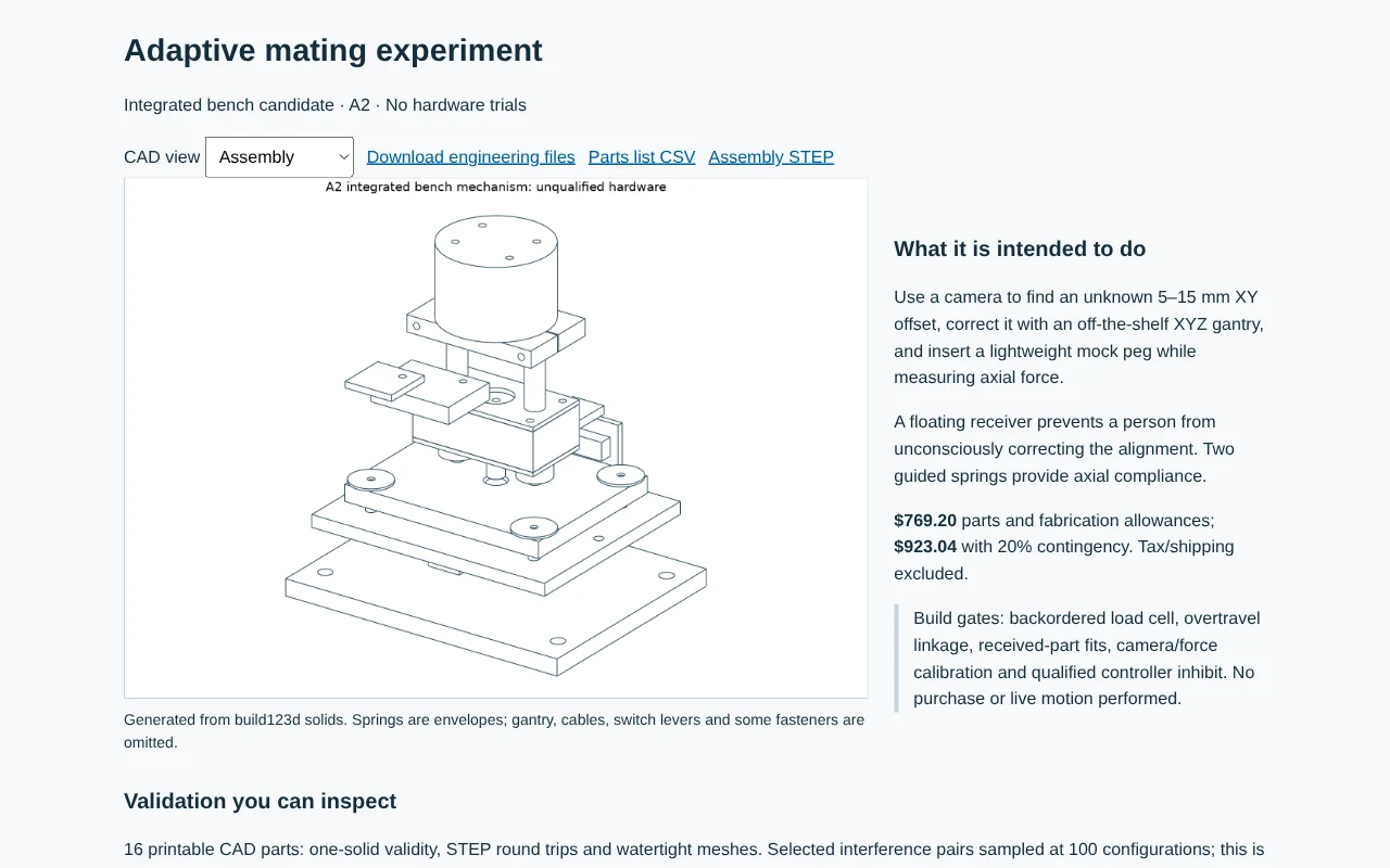
Later A1 and A2 work adds an OpenCV ArUco vision loop, bounded motion requests, force-sensor fault handling, and an integrated bench-mechanism candidate. The inspection report collects the assembly, engineering files, and validation records. The recorded 210 A1 trials use synthetic camera inputs and an analytic contact surrogate; they are not physical mating trials. A2 adds CAD and hardware-facing integration artifacts while fit, calibration, and stop-loop qualification remain open.
Building and checking it.
The next experiment is to print fit coupons, assemble the unpowered fixture, and compare two-round versus round-and-slot guides under controlled offsets and pitch error. Record capture success, jamming, final alignment, rocking, peak force, and reversibility; only then decide whether motorization would answer a meaningful remaining question.
The current checked workflow regenerates STEP/STL/PNG from source parameters and performs software geometry/export checks. Those checks prepare the physical protocol but do not substitute for its measurements.
The model excludes friction, wear, warpage, elastic deflection, thermal expansion, pin-axis tilt, several placement errors, and contact forces. The proposed 20 N force and reliability targets are experiment-specific and unverified. No real connector, payload, industrial safety case, or customer demand is established.
Source notes
Based on repository code and project records reviewed on October 30, 2026. Historical checks are described as recorded, not rerun for this article. Screenshots, renders, and mockups are labeled individually.
ai-native-hardware-rd/README.mdai-native-hardware-rd/prototype/design.mdai-native-hardware-rd/prototype/assembly-and-test.mdai-native-hardware-rd/prototype/requirements.jsonai-native-hardware-rd/validation/results.mdai-native-hardware-rd/DELIVERY.mdai-native-hardware-rd/adaptive/README.mdai-native-hardware-rd/reports/inspection/index.html