What needed solving.
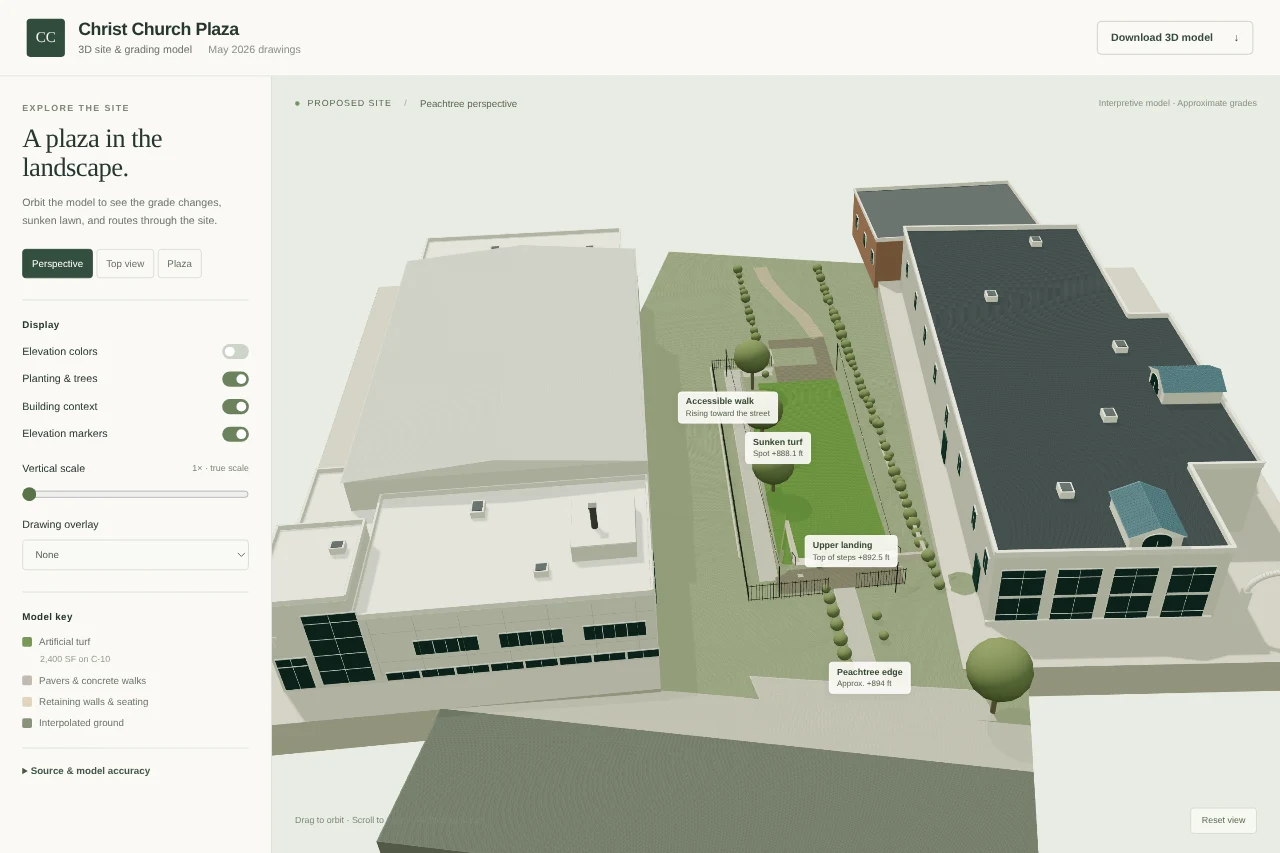
Plan sheets and spot elevations are difficult for non-specialists to connect to a three-dimensional sense of circulation, grade change, walls, stairs, and landscape. The viewer turns traced plans and interpreted elevation data into an explorable scene with drawing overlays.
- 01Plan sheets + elevations
- 02Tracing + interpreted geometry
- 033D viewer + drawing overlays
Simplified from the implementation and project notes.
How it fits together.
A Python extraction script uses PyMuPDF to collect selected PDF labels and vector outlines. The static Three.js viewer builds terrain and site geometry from traced sheet features, spot-elevation points, and interpreted grading. It includes paving, walls, steps, turf, planting, lighting, surrounding building context, elevation markers, plan overlays, and a GLB export with a stated datum.
The interface supports perspective/top/plaza views, layer toggles, vertical-scale adjustment, plan overlay placement on flat or terrain surfaces, source sheet viewing, and pan/zoom navigation. Vendored Three.js avoids runtime dependency on a CDN. Verification notes cover syntax, browser render, finite mesh coordinates, elevation colors, vertical scale, source overlay, and GLB format checks.
Source transparency is part of the interface: it points to the sheet set and discloses discrepancies between turf area annotations, the chosen later landscape layout, interpolation, and inferred architectural detail.
Building and checking it.
Open the static viewer, inspect the site from preset views, toggle planting/buildings/elevation markers and grading colors, overlay a source drawing, and navigate the sheet itself. Download the interpreted scene as GLB for review in another 3D tool.
The viewer keeps the design sheet available next to the 3D interpretation, so a reviewer can toggle overlays and compare traced boundaries or grading with their source. Elevation exaggeration is optional and clearly surfaced as a display choice.
This is an interpretive visualization, not survey, coordinated BIM, or construction geometry. Spot locations are approximated from label positions and intermediate elevations interpolated; surfaces and building context are simplified. Tree/building/light dimensions and façade details are illustrative, and underground utilities/drainage are omitted. Mobile viewport QA was unavailable per README.
Source notes
Based on repository code and project records reviewed on October 30, 2026. Historical checks are described as recorded, not rerun for this article. Screenshots, renders, and mockups are labeled individually.
christ-church-plaza-3d/README.mdchrist-church-plaza-3d/extract.pychrist-church-plaza-3d/dist/index.htmlchrist-church-plaza-3d/dist/app.js